What is power factor correction (PFC)?
Power factor correction (PFC) is the set of mechanisms built into a power supply circuit to raise the power factor (PF). PFC is commonly incorporated into computer power supplies to increase their PF. A circuit’s PF is the ratio of real power to apparent power. The higher the PF, the more efficiently that the electrical current is being used.
There are three types of power in an electric circuit:
- Real power (P). Real power is the amount of usable energy that can be transferred to a load. It is typically a percentage of the total amount of available power. If the load is entirely resistive, all power is considered real power, although this is rarely the case. Real power, which is measured in watts (W), is also referred to as active power, true power or usable power.
- Reactive power (Q). This is power that operates at right angles to real power. It is used to generate and maintain magnetic fields in reactive components, such as inductors or capacitors. Reactive power does not go into the load like real power and is instead pumped back to the grid, where it can impact power quality. Ideally, a circuit’s load should have a low amount of reactive power to maximize energy efficiency and reduce energy costs and waste. Reactive power is measured in volt-ampere reactive.
- Apparent power (S). This is the combination of real and reactive power, measured in volt-ampere (VA). It is the full amount of energy a circuit consumed. Electric companies charge for power based on this amount, even though the circuit consumes only the real power.
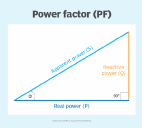
Figure 1 provides a conceptual overview of how real, reactive and apparent power fit together; it shows how apparent power is composed of both real power and reactive power. For most of today’s circuits, the goal is to minimize the amount of reactive power in the circuit’s load so it is only a small percentage of the overall apparent power.
This ratio between real and apparent power can be used to calculate a circuit’s PF. Because real power is a portion of apparent power, you can divide the real power (W) by the apparent power (VA) to determine the PF:
Power factor = real power / apparent power
The PF value is always between 0 and 1. Most circuits aim for a PF greater than 0.9. A standard power supply has a PF of 0.70-0.75, but a power supply with PFC has a power factor of 0.95-0.99. Many countries now regulate the acceptable PF in most circuits.

The relationship among real, reactive and apparent power can also be represented as a right triangle, with the real and reactive sides forming the right angle, as shown in Figure 2. The 90-degree angle between real power and reactive power is indicated by the rectangle. The angle between real power and apparent power is indicated by the curved arrow and the Greek letter phi (Ф).
The triangle points to another method for determining a circuit’s PF. With this approach, you need only find the cosine of the angle between real power and apparent power:
Power factor = cos(Ф)
Manufacturers commonly incorporate PFC into their circuits to increase the PF, using different techniques in their circuits. Two of the most common techniques are passive and active:
- Passive PFC. This approach uses passive filtering to remove the harmonics, thereby increasing the PF. Passive PFC is inexpensive and simple to implement, but the components can be heavy and bulky. It is also limited to low-power applications.
- Active PFC. This approach modulates the waveforms to reduce the reactive power. The components are smaller and lighter than passive PFC and more efficient. They can also deliver a higher PF and handle a greater range of input voltages. However, this approach costs more and is more complex to implement. Active PFC supports both single-phase and three-phase systems.
PFC is not used solely for power supplies. In other industries, PFC mechanisms help to reduce the reactive power produced by fluorescent and high bay lighting, arc furnaces, induction welders and equipment that uses electrical motors. Energy efficiency is increasingly important for organizations pursuing green computing as part of their efforts to fulfill the goals of environmental, social and governance initiatives.
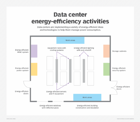
Building lighting, as well as heating and cooling systems, are important factors in data center energy efficiency. Other considerations include server efficiency, computer cooling systems and many aspects of building construction, including doors and windows.

Learn about green computing best practices and how to put them into practice.


